If you haven't seen the first part of the project. I highly suggest you read it.
You will have a more global view of what I am doing.
Prototype I, II, III
Prototype I, II, III
Prototype IV : upgrading prototype III
Goal
The goal of prototype IV will be to resolve all the problems of prototype III, which means :
decreasing the loading time of the cannon, adding 2 additional cannons to divide the loading
time by 3, changing the code, so I can control 2 or more motors at the same time, changing the rotational
mechanism so the robot could be more precise, combining shift registers with stepper motors. The automation
will happen in prototype V. For now, I will try to control the robot using a remote controller.
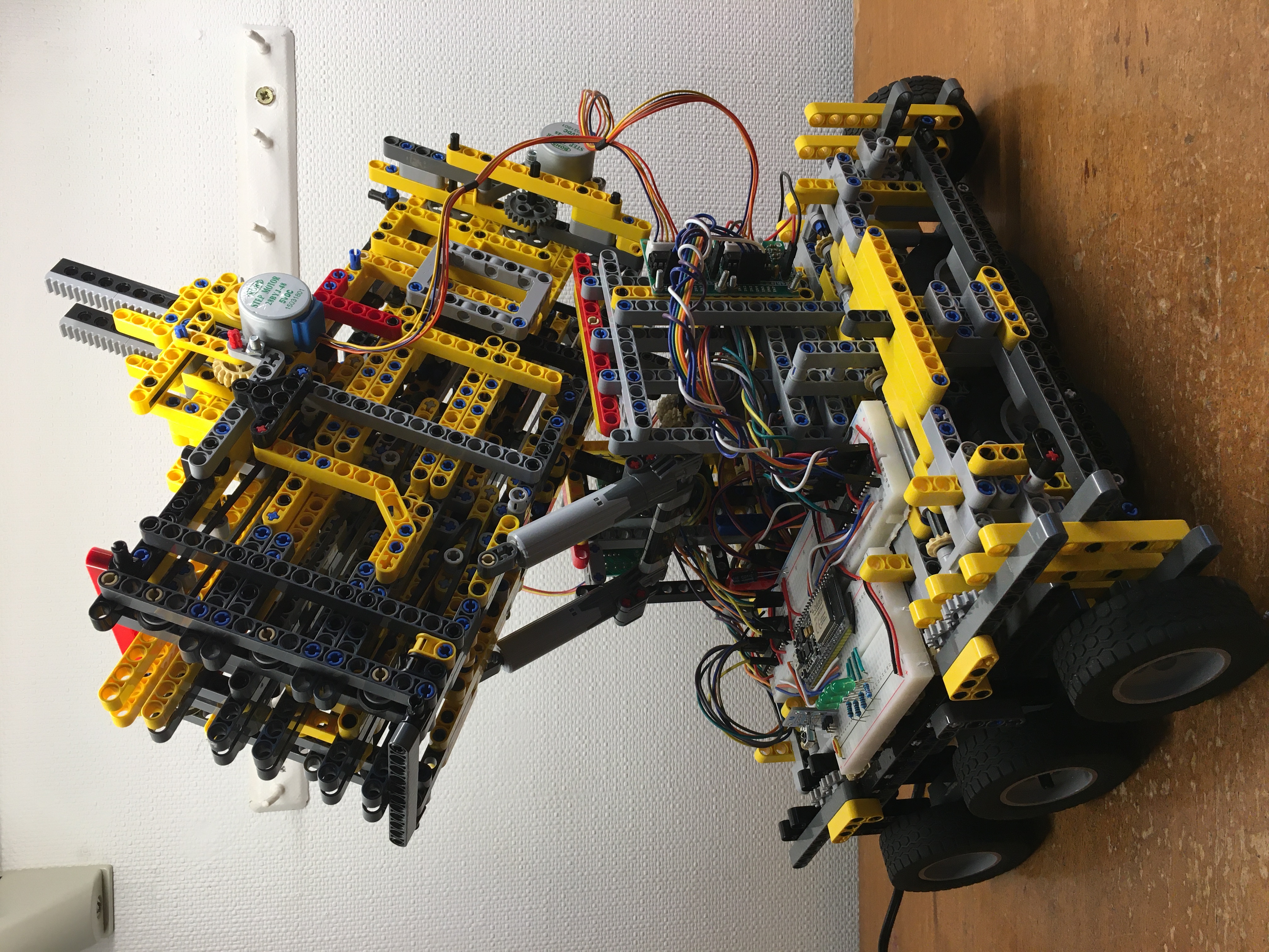
Building the lower part
In prototype III, I told you that the robot has a problem with the horizontal aiming system.
The fact was that the robot had to rotate on hisself to aim. That is not a good solution.
I tried adding chains. The robot could then move in all directions. The problem with such a system is
that you need a rough floor. Another big issue is that it is really complicated to automate a tank in the
sense that the tank won’t always be positioned perpendicular to the dart board.
The solution I found was to use wheels. To make sure the robot could move in any direction, I decided to
place wheels in both directions, perpendicular to each other. The wheels can’t rotate on themselves. The
next thing I had to include was a system where the robot could lift the wheels in one direction otherwise
the robot would never have the possibility to move. That has also a big advantage, when I am ready to shoot,
I can stabilize the robot by placing the wheels on the same height.
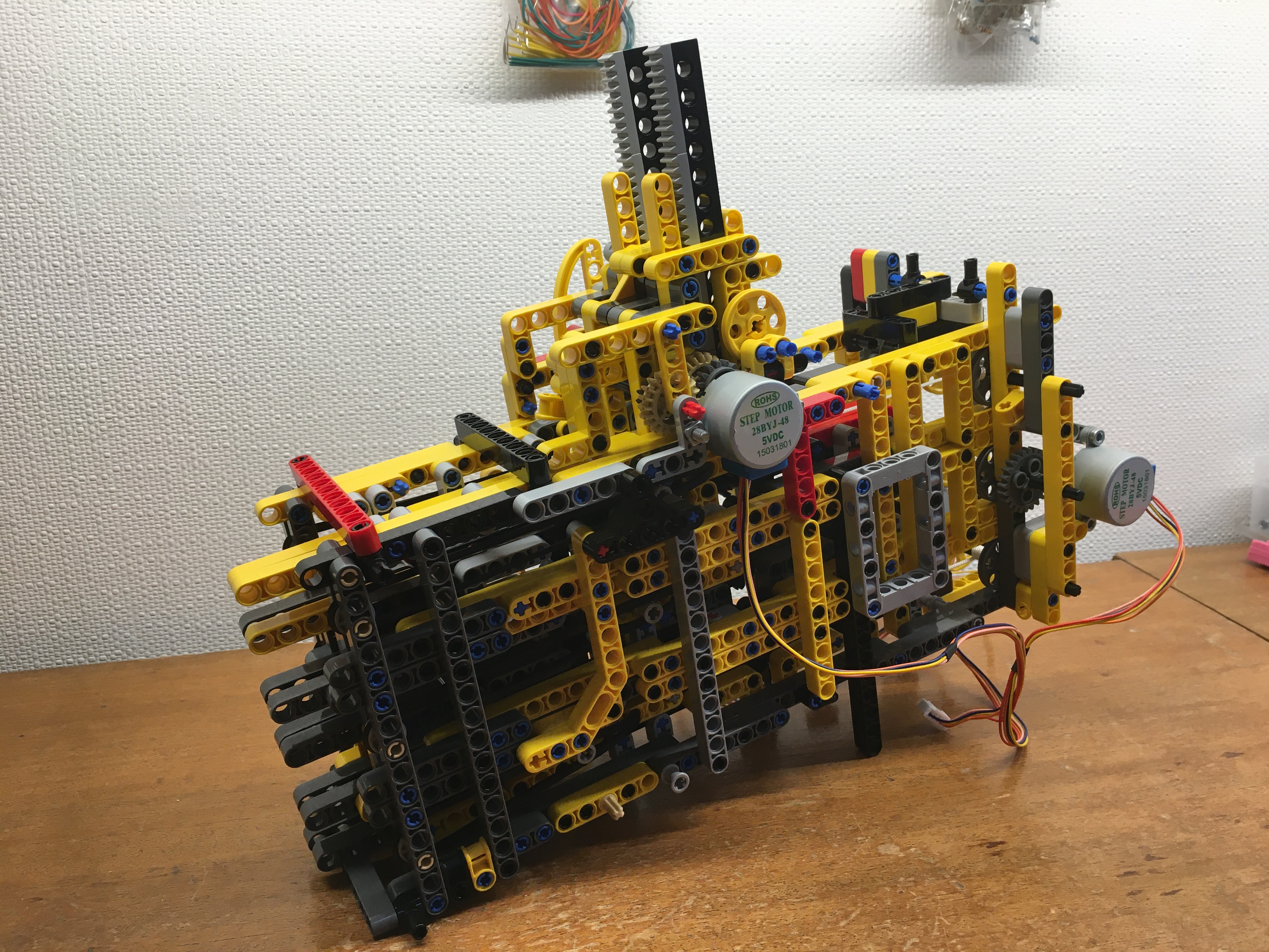
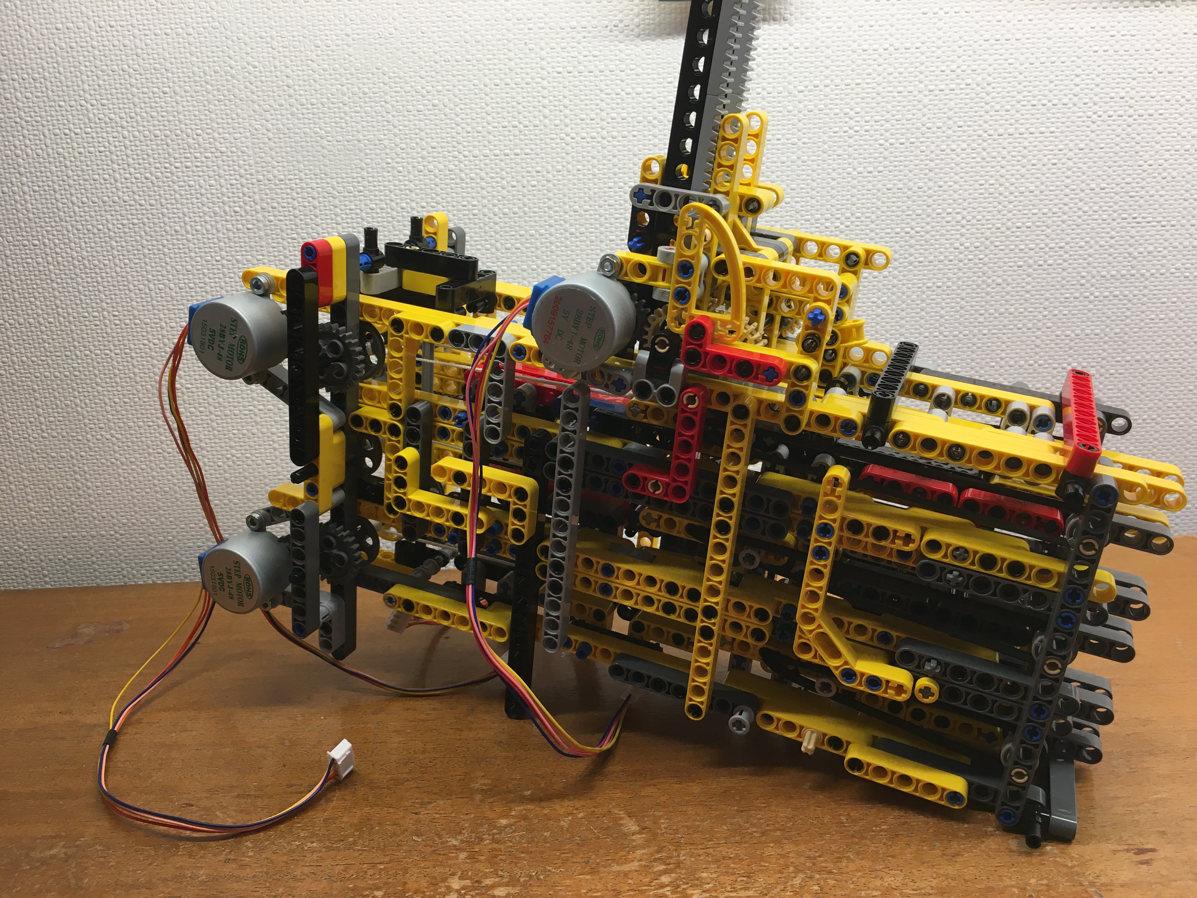
Building the cannon
The cannon has been improved, in the sense that there are now 3 cannons instead of one. The main reason why 3
is because to play darts you have to throw 3 darts before the other one can play. Because I switched the elastics
for some smaller ones, I could now use only one stepper motor to load one cannon. Instead of using one trigger for
each cannon, I decided to put one big trigger controlled by a stepper motor instead of a servo motor.
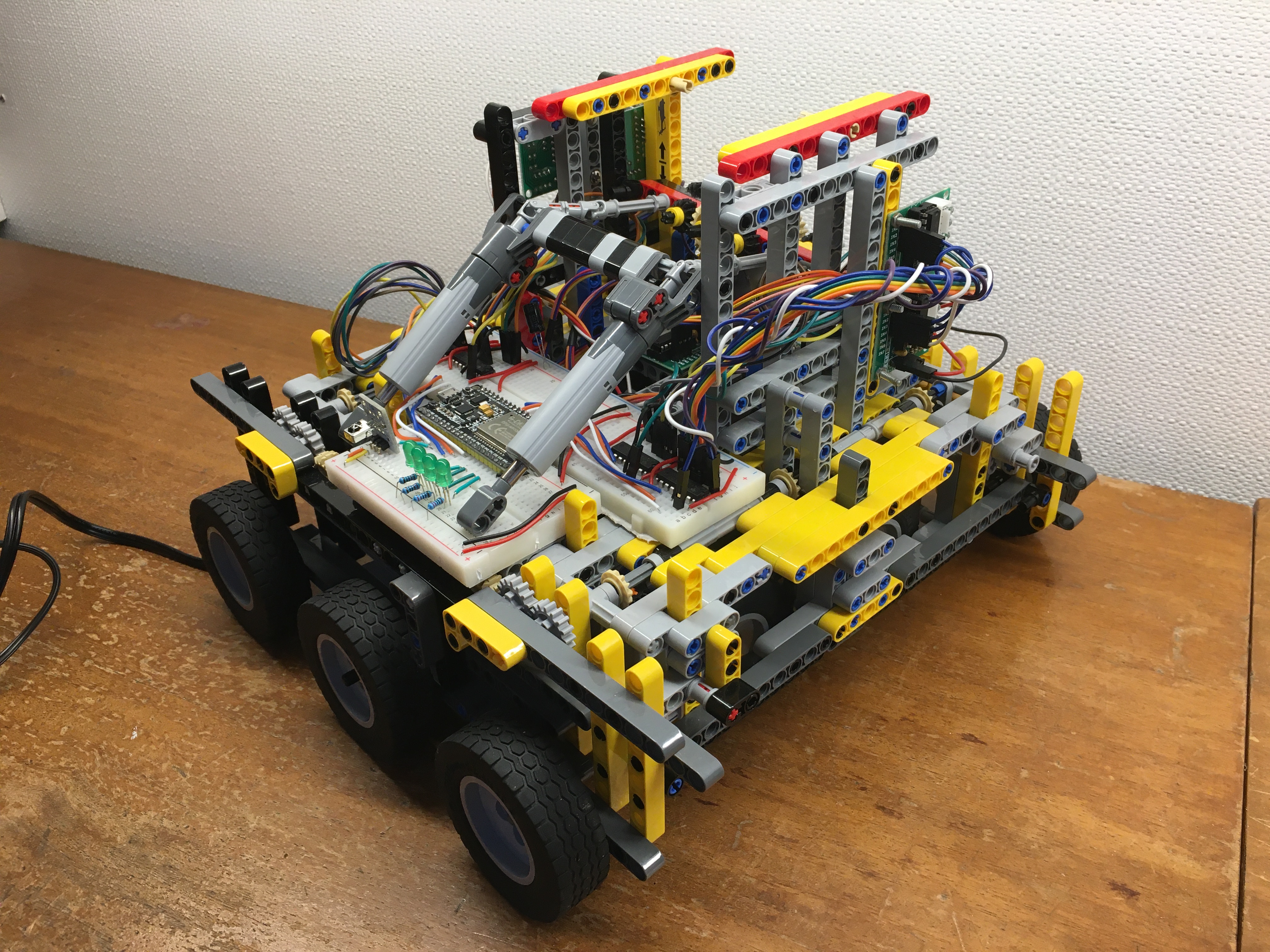
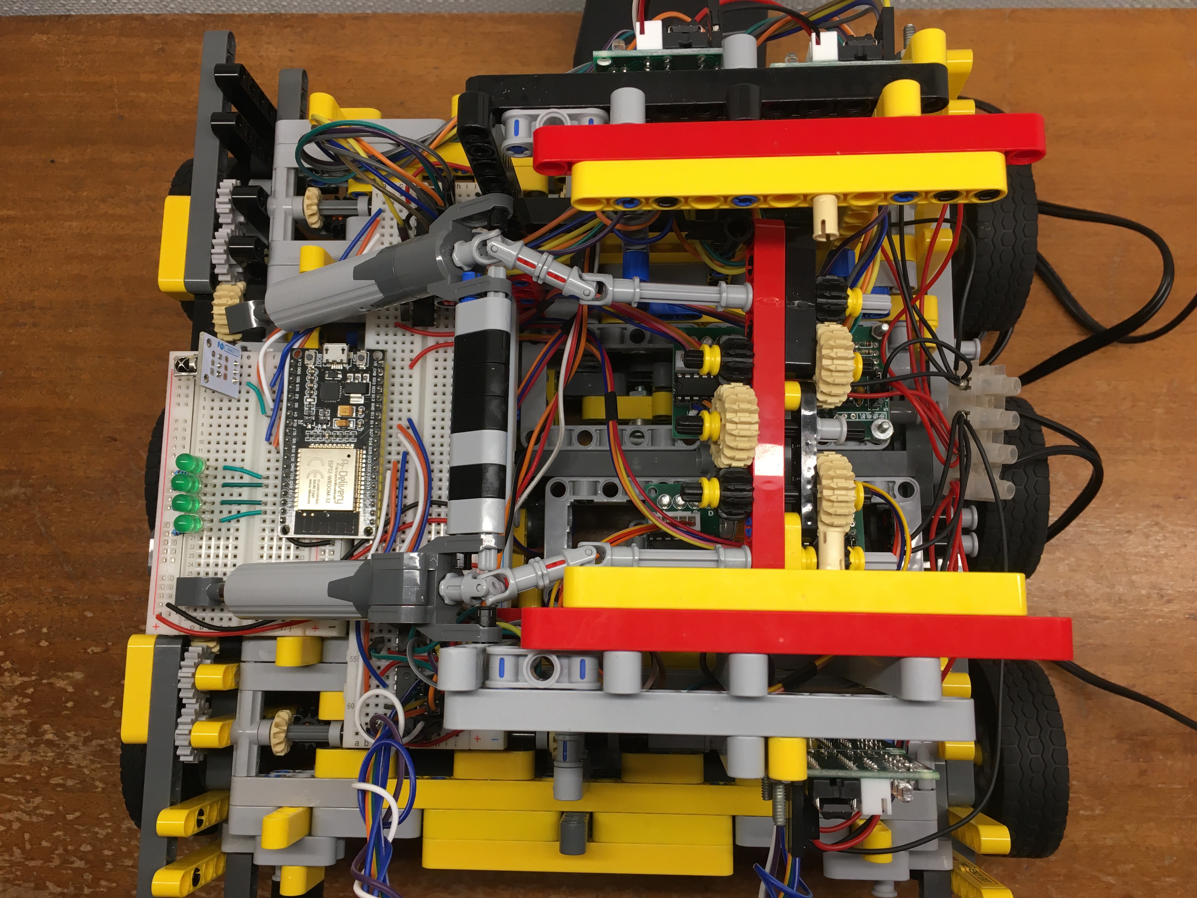
Electronic part
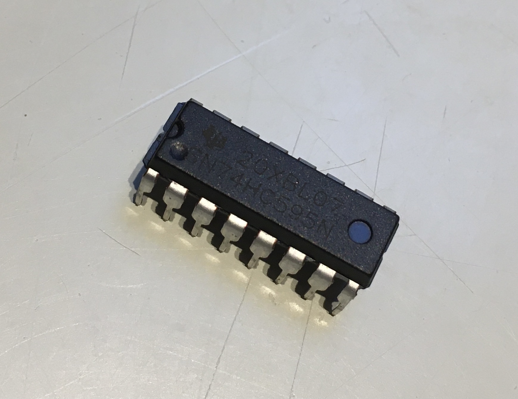
For the electronic part, I decided to use an ESP32 instead of an Arduino UNO. The whole system uses 8 different
motors (3 for the wheels, 3 for the cannons, 1 for the trigger and 1 for the angle). Because each motor has to be
controlled by 4 pins, I normally had 32 pins to control. Which is way too much. So I had to use a shift register.
More precisely a SIPO (serial in, parallel out) shift register.
The way it works is by sending him a byte of data. He will then split it in 8 values (1 or 0). If the value is 1,
then the shift register (which contains 8 parallel out pins), will send current to the pin corresponding to the
index on which the value equals 1. If it’s 0, he won’t send any current. So for example if we send byte
[0][1][0][1][0][1][0][1], the shift register will send current to the pins number 1, 3, 5, 7 (we start at index 0).
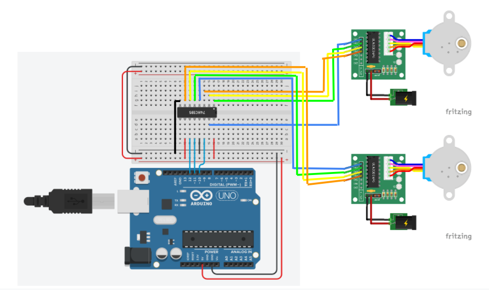
A shift register needs 3 pins to work but you can control 8 pins with it. So for now, I can control my 8 motors using
only 12 pins on the esp32.
Now using a shift register to control a stepper motor is not that easy. Normally I would have used a library to control it, but here it is impossible. So I started searching, and by investigating the source code of the stepper.h library (link), I found something interesting. A stepper motor like any other motor, turns by alternating the magnetic field using some coils. Now this alternation has to happen in a precise order at a precise moment to make it turn. What I found out in the source code was the order in which the coils have to be alternated for the type of stepper motor I use.
Because it’s is in a loop, I can put the data in an array, and control it by using a for loop.
        const byte latchPin1 = 18;    // ST_CP pin 18     // uno = 11
        const byte clockPin1 = 5;     // SH_CP pin 5     // uno = 12
        const byte dataPin1 = 19;     // DS pin 19        // uno = 10

        const char motorCW1[] = {B10000000, B11000000, B01000000, B01100000, B00100000, B00110000, B00010000, B10010000};
        const char motorCW2[] = {B00001000, B00001100, B00000100, B00000110, B00000010, B00000011, B00000001, B00001001};
        const char motorCCW1[] = {B10010000, B00010000, B00110000, B00100000, B01100000, B01000000, B11000000, B10000000};
        const char motorCCW2[] = {B00001001, B00000001, B00000011, B00000010, B00000110, B00000100, B00001100, B00001000};


        void setup() {
          pinMode(latchPin1, OUTPUT);
          pinMode(clockPin1, OUTPUT);
          pinMode(dataPin1, OUTPUT);
        }

        void loop() {
          for(int i = 0; i < 8; i++) {
              digitalWrite(latchPin1, LOW);
              shiftOut(dataPin1, clockPin1, MSBFIRST, (motorCCW1[i]));
              digitalWrite(latchPin1, HIGH);
              delay(1);
            }
        }
To control the motors, I firstly tried it with some potentiometers like in prototype III, unfortunately there were too many errors (probably because the potentiometers were too cheap). They also needed a lot of pins. I then came to the idea of using the infrared controller. It is a good alternative because you can control it at distance and because it only requires 1 pin. I then added 4 leds to it, they give me the information about how many buttons are now pressed on the controller. Here you can find the entire electronic circuit :
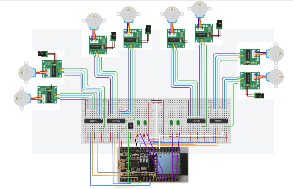
I won’t explain the entire code here, but you can find it on github. I even placed a lot of comments on it so I hope you won’t be lost.