Environmental technology : oxygen filter
Introduction
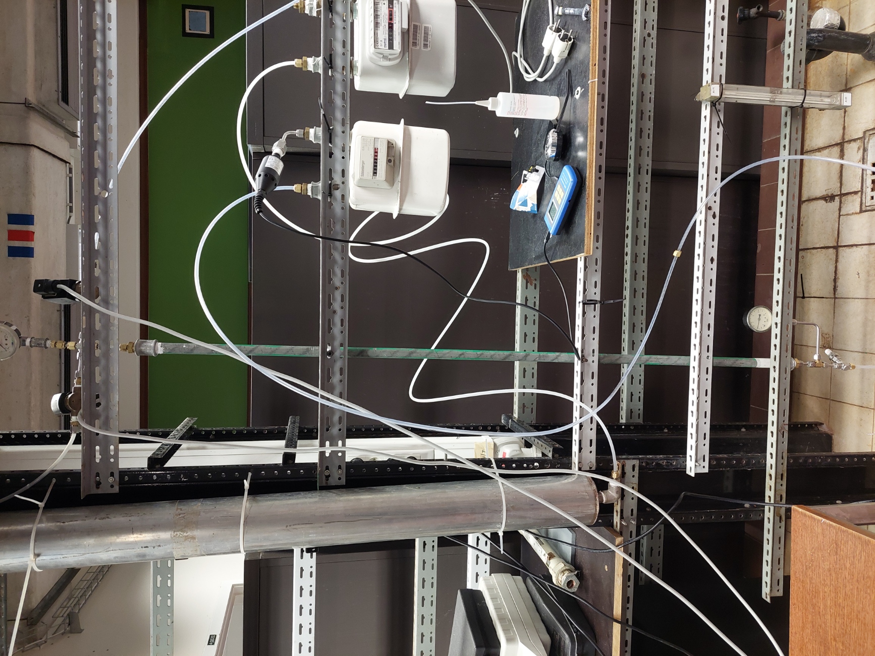
Air is composed of 78% of nitrogen and 21% of air with 1% of other gasses. Our task was to build a device capable of filtering the oxygen from the air to get higher purity rates. Our mission was to get to a flow rate of 70l/h with a purity of 40% O2 and a flow rate of 10l/h with a purity of 75%. So it has to be versatile. Purification of air has many useful cases like in hospitals and the food industry.
The first thing we did was examining several existing technics for air filtering. We examine Pressure Swing Adsorption, Temperature Swing Adsorption (TSA), membrane separation and cryogenic distillation. Due to the time we have and the expectancy we need to fulfill we quickly found out that PSA our Pressure Swing Adsorption was the best system.
The first thing we did was examining several existing technics for air filtering. We examine Pressure Swing Adsorption, Temperature Swing Adsorption (TSA), membrane separation and cryogenic distillation. Due to the time we have and the expectancy we need to fulfill we quickly found out that PSA our Pressure Swing Adsorption was the best system.
PSA
PSA work by the principle of adsorption where specific molecules will get stuck under pressure while the other molecules will be able to move though some adsorbent molecules. The idea is that by using 2 pipes and several interconnection. We will be able due to the differential in pression between the 2 pipes to filtrate and clear the pipes by changing the pression at different times using automated valves.
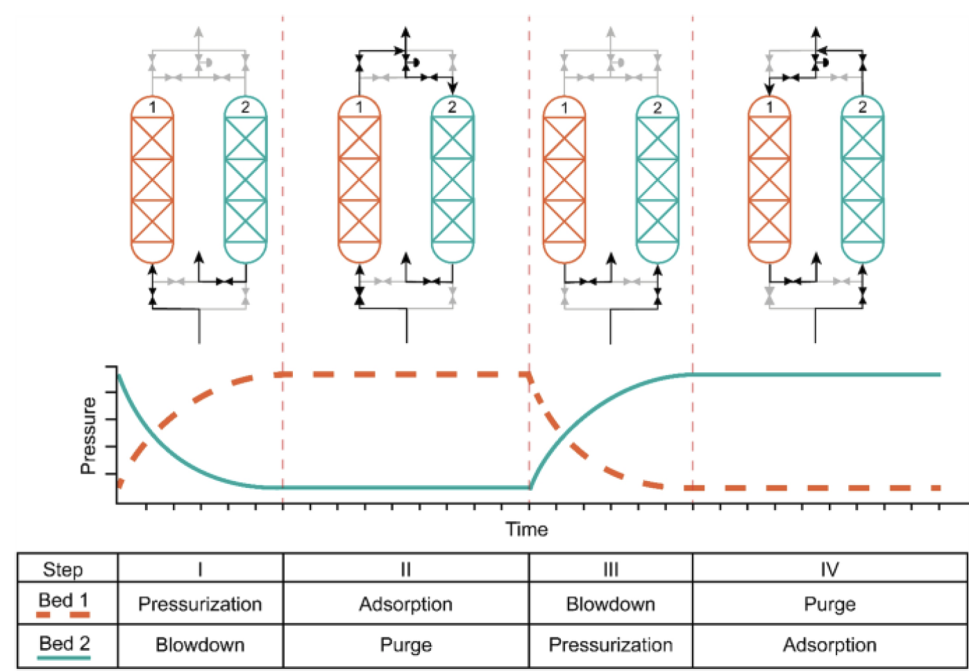 See link for more reference.
Essential for this technic to work is to use the appropriate absorbent molecules. Several materials where discussed like active alumina, active carbon, carbon molecular sieves and silicon gel. At the end we decided to use zeolites as these are the easiest and cheapest materials to use. Those are minerals made out of aluminum, oxygen and silicium in a special molecular structure. In the zeolites there exist several types. Some contains more aluminum or are bigger than others. These can have huge effect on the efficiency of the zeolites to adsorbate molecules. We decided to use the 5A zeolite. See link for more information.

Humidity of adsorbants
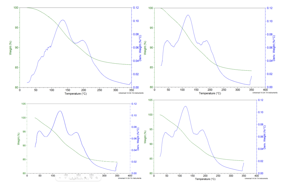
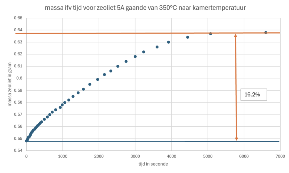
One major problem when using zeolites is that their capability to adsorbate molecules is highly dependent of the humidity of the absorbent molecules. Air contains also humidity and so we had to know the effect of it. We made several tests with TGA (thermosgravimetric analysis) and using a more simple method with a weight. We came to the conclusion that around 16m% water could be adsorbed by the zeolite which means that less nitrogen could be adsorbed when the zeolites are not fully dry.
The mechanism of opening and closing the valves between the two pipes can easily be found on internet. But they all have a major problem. They are complex in building and optimizing. They also need a lot of time to get to equilibrium which in our 3 days of testing will be to short. Therefore we decided to go for RPSA of Rapid Pressure Swing Adsorption. This one has as main advantage the fact that it uses only one pipe and 2 valves. The diagram of our system can be found on following picture.

PSA process
Because humidity is essential for the zeolites we will use dry air coming from the VUB. The idea is that dry air at a pression of 4 bar comes from the top right side. Once the feed valve is open, it can enter the pipe full of zeolites. The feed valve closes around 1 seconds after opening. Due to the differential of pression the zeolites will block a certain amount of nitrogen and let pass another amount of oxygen though the pipe. After a second the purge valve is open and so the pipe is cleaned because now the stuck nitrogen gas wants to go the left side tank (buffer vat) where the pression is lower. This occur for a couple of seconds before the purge valve is closed and the cycle starts again. The needle tap (naaldkraan) is there to make an even bigger differential of pression between the top and bottom of the pipe. Closing it will cause a smaller flow rate but a bigger purity level. At the end an oxygen sensor is placed to get the concentration. 2 flow rate sensors calculate the outcoming flow rate.
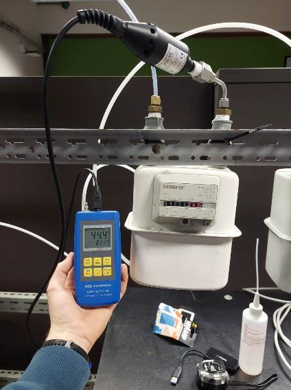 The optimalisation of this process consist of changing the different times where the valves are open and closed. This has manly to be tested and optimized using our logics and not really calculations even though several systems like Langmuir can help understanding it. Other parameters like temperature and feed pressure are not discussed on this page.
Other parameters like the bad length and the dimensions of the buffer tank have been calculated manually.

Building process

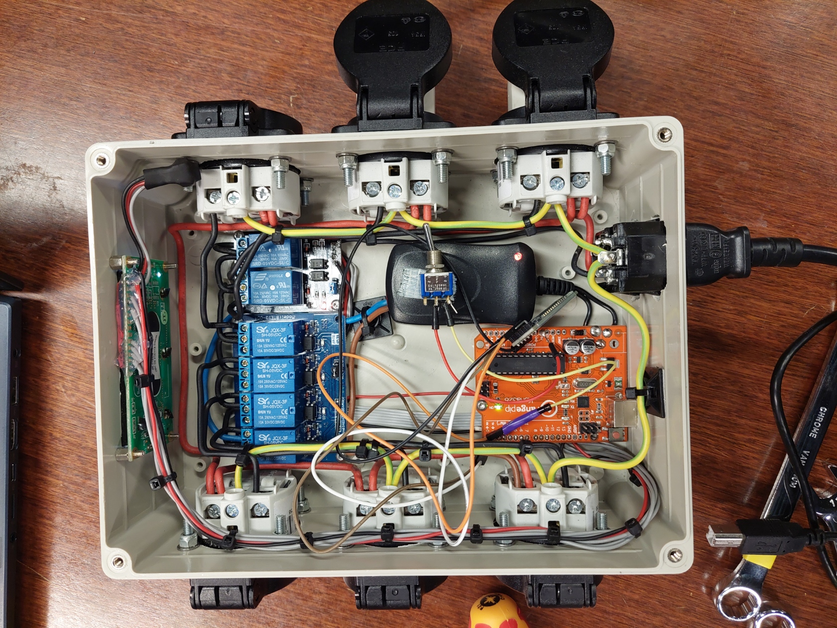
The operating principle of a relay is similar to that of a transistor or electronic button. A small voltage at the input ensures the on and off of a large connection to which mains voltage is applied. A relay can be used both in Normally On (NO) and in Normally Close (NC). To control the relay a digital pin on from an Arduino can be used. The Arduino "Uno" used here has 14 of these pins. Pin numbers 2 to 13 can be used for this application. Pins 0 and 1 are reserved for serial communication. These can also be used as digital output like the other pins, only then no communication can take place between the Arduino and another device such as a computer via the serial communication. The device consists of 6 relays for which 6 digital outputs are required.
In addition, we also find an LCD screen. In this configuration, this also requires 6 digital pins. The LCD screen is then easily controlled by a library such as LiquidCrystal.h. This means that all outputs between pin 2 and 13 are used. If we wanted to change the times at which the valves go on and off, we would have to reprogram the Arduino every time, which is not efficient. This also requires a computer on which Arduino code can be written every time. Fortunately, there are a few solutions for this. The goal would be to be able to manually change the time interval of each step in the process on the device without having to adjust the Arduino code.
The first solution would be to add potentiometers. The potentiometers can be connected directly to the analog pins of the Arduino. It has 6, which is more than enough for the different times that we want to change. The disadvantage is that the potentiometers have to be of good quality to prevent incorrect readings. Another problem would be that holes have to be made in the lid and that would be a shame if this idea would turn out to be disappointing. If we had had more time, an option would have been to print an extra lid using a 3D printer.
Another solution would be to add buttons. These have to be connected to the digital pins of the Arduino. For the time being, there is no room for that. A solution to use less pins would be to use an I2C converter so that the LCD screen would only have to work with 2 pins instead of 6. A PISO (parallel in, serial out) converter such as the 74HC595 can also be used to operate 8 outputs with 3 digital pins. The pins that remain can be used to add buttons. The disadvantage here is that holes have to be made in the cover to operate the buttons. A large part of the electrical diagram must also be revised to be able to add these components. This would also mean that we would have to solder everything again. The architecture of the Arduino code would also have to change, which would increase the necessary coding time.
Therefore, it was considered to find a simpler solution that did not require any modifications to the lid and did not require any major changes to the electrical circuit. Ideally, the device should be able to be controlled remotely. Using an infrared controller would be an easy option, since we only need 1 digital pin for that. The problem with this is that infrared signals do not pass through solids and therefore cannot pass through the lid.
It was then decided to work with a Bluetooth module in the hope that we would be able to control the device with our smartphone. The Bluetooth module in question is the HC-05 module. In addition to the Vcc and the ground, this also requires 2 digital pins to exchange information. These must be the rx and tx pins of the Arduino. The two pins that remained must therefore be used for this specific module!
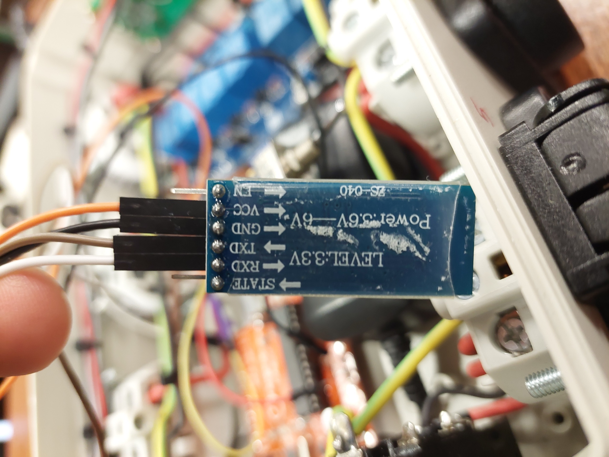 The next step was to design an app that could communicate with the Arduino module. For this, it was decided to use the M.I.T. App Inventor website, which makes it easy to develop an application for a smartphone. The images below show the layout and the logic behind the final application.
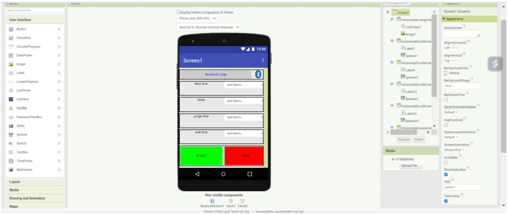
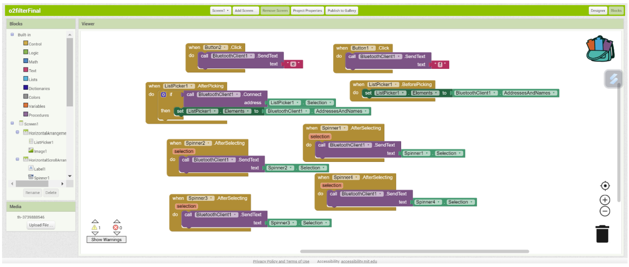 There are 4 spinners that all have elements like “a500”, “a1000”, etc. This data is then sent via Bluetooth to the device. To connect it, the “bluetooth code” button must be pressed and then the correct connection must be checked. In the Arduino code that can be found underneath, the intention is to first make a distinction between the first characters. If this is an “a” then we know that the next 3 characters will be the new choice for the feed delay in milliseconds. Analogous for “b” and “c”, only these are then for the delay and the purge time. The “start” and “stop” buttons in the app are then used to start or stop the sequence. These send the letter “e” and “f” to the Arduino.
In addition, we also find an LCD screen. In this configuration, this also requires 6 digital pins. The LCD screen is then easily controlled by a library such as LiquidCrystal.h. This means that all outputs between pin 2 and 13 are used. If we wanted to change the times at which the valves go on and off, we would have to reprogram the Arduino every time, which is not efficient. This also requires a computer on which Arduino code can be written every time. Fortunately, there are a few solutions for this. The goal would be to be able to manually change the time interval of each step in the process on the device without having to adjust the Arduino code.
The first solution would be to add potentiometers. The potentiometers can be connected directly to the analog pins of the Arduino. It has 6, which is more than enough for the different times that we want to change. The disadvantage is that the potentiometers have to be of good quality to prevent incorrect readings. Another problem would be that holes have to be made in the lid and that would be a shame if this idea would turn out to be disappointing. If we had had more time, an option would have been to print an extra lid using a 3D printer.
Another solution would be to add buttons. These have to be connected to the digital pins of the Arduino. For the time being, there is no room for that. A solution to use less pins would be to use an I2C converter so that the LCD screen would only have to work with 2 pins instead of 6. A PISO (parallel in, serial out) converter such as the 74HC595 can also be used to operate 8 outputs with 3 digital pins. The pins that remain can be used to add buttons. The disadvantage here is that holes have to be made in the cover to operate the buttons. A large part of the electrical diagram must also be revised to be able to add these components. This would also mean that we would have to solder everything again. The architecture of the Arduino code would also have to change, which would increase the necessary coding time.
Therefore, it was considered to find a simpler solution that did not require any modifications to the lid and did not require any major changes to the electrical circuit. Ideally, the device should be able to be controlled remotely. Using an infrared controller would be an easy option, since we only need 1 digital pin for that. The problem with this is that infrared signals do not pass through solids and therefore cannot pass through the lid.
It was then decided to work with a Bluetooth module in the hope that we would be able to control the device with our smartphone. The Bluetooth module in question is the HC-05 module. In addition to the Vcc and the ground, this also requires 2 digital pins to exchange information. These must be the rx and tx pins of the Arduino. The two pins that remained must therefore be used for this specific module!


Conclusion
Once our device was made and ready to operate. We could start optimizing and testing it. By tuning the timings one by one we first tried to get the highest concentration of oxygen. We came to a flow rate of 11 l/h with a concentration of 81.1%. On the other hand by changing the timings we quickly got the objectives of a flow rate of more than 70L/h with a purity of 40%.